PIN-CLIP ---> It's for the DIYer , this kit come with FULL PINs for support almost chips, after the complete soldering then can plug and play, don't need solder to the wii mother board at all.
So the point of PIN-CLIP is : You don't need solder anything to your Wii motherboard, keep your Wii more safe and don't lost the guarantee, and easy for replace with other chip!
Discuss : http://wiinewz.com/forums/infectus-argon-wiiktus/67864-the-universal-pin-clip-released.html
The PIN-CLIP looking
The packing
AFTER soldering the complete chip, then can plug to the chipset for run.
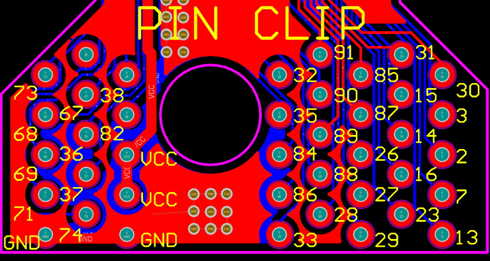
The chipset pin number diagram, some example:
The ARGON need solder to these PIN-CLIP point number:
| R | A | RST | B | F | G | I | C | D | E | H | VCC | GND |
| #2 | #3 | #82 | #84 | #85 | #86 | #87 | #88 | #89 | #90 | #91 | #VCC | #GND |
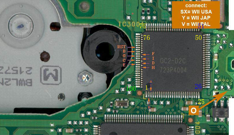
The INFECTUS 9 wires chip need solder to these PIN-CLIP point number:
| U | M | N | P | Q | T | O | 5V | GND |
| Solder to board | #73 | #74 | #84 | #85 | #91 | Solder to board | Solder to board | #GND |
The old D2PRO install diagram: 13/15/19 wires:
| E | D | C | 9 | P | N | M | L | K |
| #2 | #3 | #26 | #38 | #82 | #84 | #85 | #86 | #87 |
| J | H | G | F | 5,6,7,8 | VCC | GND |
| #88 | #89 | #90 | #91 | Solder to board | #VCC | #GND |
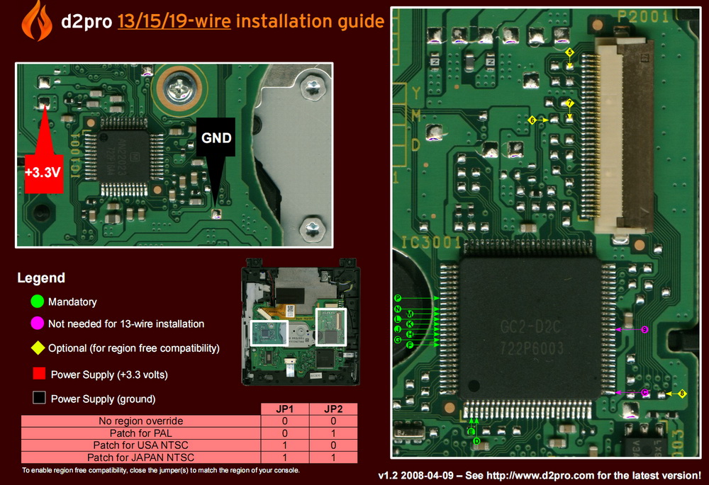
The D2PRO 9 wires chip need solder to these PIN-CLIP point number:
| C | G | H | F | E | D | J | VCC | GND |
| Solder to board | #73 | #74 | #84 | #85 | #91 | Solder to board | #VCC | #GND |
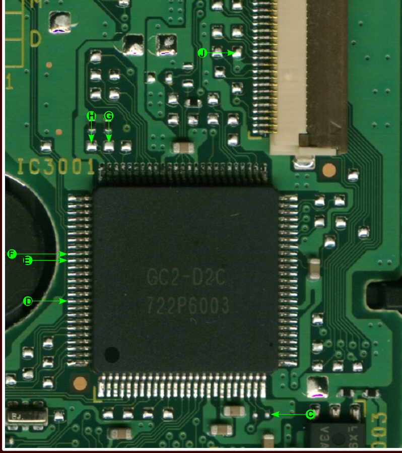
The WII LIKEIT 9 wires chip need solder to these PIN-CLIP point number:
| B | M | N | T | U | V | Z | VCC | GND |
| #23 | #73 | #74 | #84 | #85 | #91 | Solder to board | #VCC | #GND |
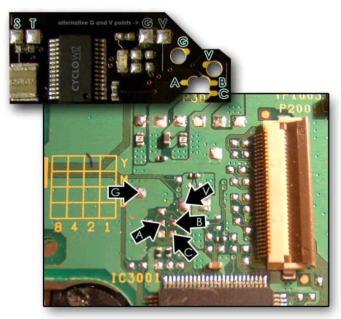
The CYCLOWIZ need solder to these PIN-CLIP point number:
| A | B | C | V | G |
| #69 | #67 | #68 | #VCC | #GND |
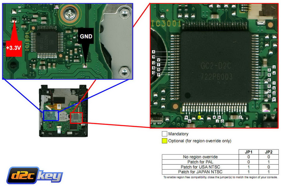
The D2CKEY install diagram: 31 wires:
| N | M | L | K | J | H | G | Z | F | E | D | C | 9 | 8 | 7 | 6 |
| #2 | #3 | #7 | #13 | #14 | #15 | #16 | #23 | #26 | #27 | #28 | #29 | #30 | #31 | #32 | #33 |
| 5 | 4 | 3 | 2 | X | W | V | U | T | S | R | Q | P | VCC | GND |
| #35 | #36 | #37 | #38 | #82 | #84 | #85 | #86 | #87 | #88 | #89 | #90 | #91 | #VCC | #GND |
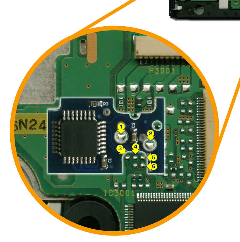
The WIIKEY install diagram: 6 wires:
| 1 | 2 | 3 | 4 | 5 | 6 |
| GND | VCC | #71 | #69 | #67 | #68 |
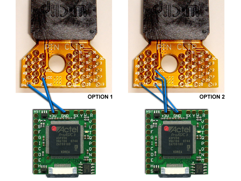
The PIN-CLIP pin map, Click the photo for enlarger it
Q&A
Q: I have bought your PIN-CLIP and are going to
install my Argon SPI 9 wire modchip to it. I have a question about this because
the PIN-CLIP has two GND and two VCC connections. The Argon operates at 3V but
there is no 3V connection on the PIN-CLIP, I assume the VCC connection is the
same? Since I don’t have thicker Kynar wire for the power and ground connections
I’m just going to twist two AWG30 Kynar wires together. What is in this case the
best way to solder these twisted wires to the PIN-CLIP? Take a look at the
included image that I made and tell me which option you recommend for soldering
the VCC and GND connections of the PIN-CLIP to the Argon.
A: OPTION2 is better.
